System Overview
What Is ESP-GUARDX?
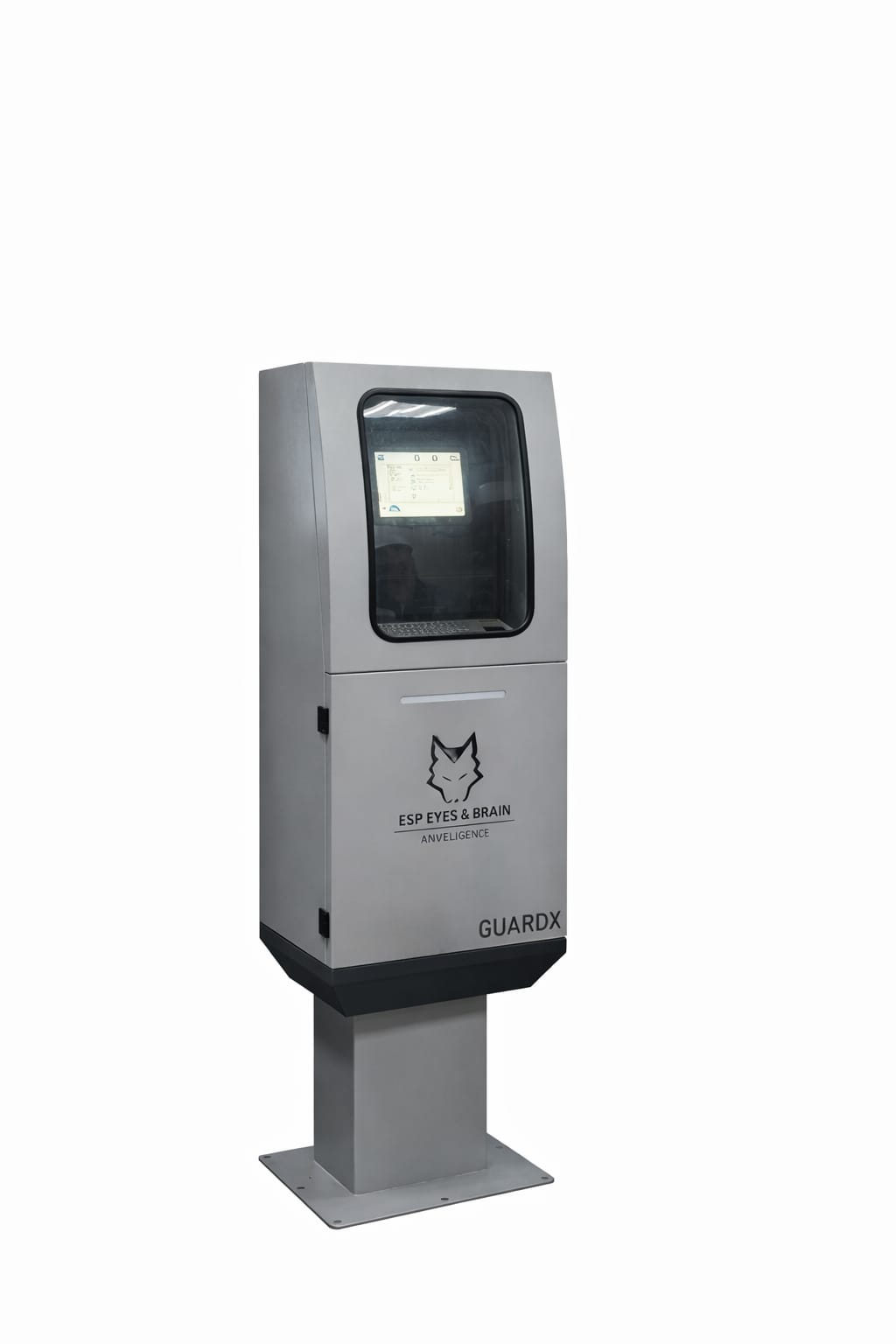
ESP-GUARDX is an embedded monitoring and control system designed for Electric Submersible Pump (ESP) installations in oil and gas fields. It runs on a dedicated industrial touchscreen device and provides:
- Real-time electrical and mechanical parameter monitoring
- Automatic fault detection and event recording
- Well production optimization (Through AI)
- ESP health assessment
- Well production tracking
- Monitors external parameters through modbus and plc
- Capable of connecting additional sensors through plc
- Measures and monitors power quality issues
Visual overview
For the internal hardware layout, the functional block diagram, and the signal acquisition flow, see the System Diagrams page.
System Architecture
The system consists of three main layers:
1. Data Acquisition Layer
ESP-GUARDX samples electrical signals at up to 40 MHz through a high-speed SPI (Serial Peripheral Interface) bus. Six rectifier boards in the Electronics enclosure carry the analog front end:
- 18 voltage channels — six rectifier boards × three phases
- 24 current channels — six rectifier boards × four current inputs (three phase + one auxiliary)
Each data packet contains:
| Data Type | Samples per Packet |
|---|---|
| Waveform (graph) data | 4,096 samples |
| Harmonic data | 808 values |
| Power measurements | 24 parameters |
Data packets are processed at a rate of 5--10 Hz (every 100--200 ms), providing continuous real-time updates.
2. Processing Layer
The processing layer runs on an embedded industrial processor and handles:
- Signal Processing -- RMS calculation, harmonic decomposition, phasor analysis
- Event Detection -- Real-time threshold comparison against user-defined warn and trip levels
- Data Logging -- Automatic data logging and event recording
- Pump Calculations -- Affinity law computations, polynomial curve fitting
- Motor Analysis -- Load factor, efficiency, power factor interpolation
3. Display Layer
The touchscreen interface provides:
- Interactive dashboard with live gauges and indicators
- 8-channel oscilloscope waveform display at 60 FPS
- Pump performance curve charts
- Motor efficiency plots
- Event list and waveform replay
- Settings and configuration screens
Supported Communication Protocols
| Protocol | Use Case |
|---|---|
| SPI | High-speed ADC data acquisition (40 MHz) |
| UART | Serial sensor communication (9600 baud) |
| Modbus RTU | Industrial device communication over RS-485 |