Hardware Requirements
Device Specifications
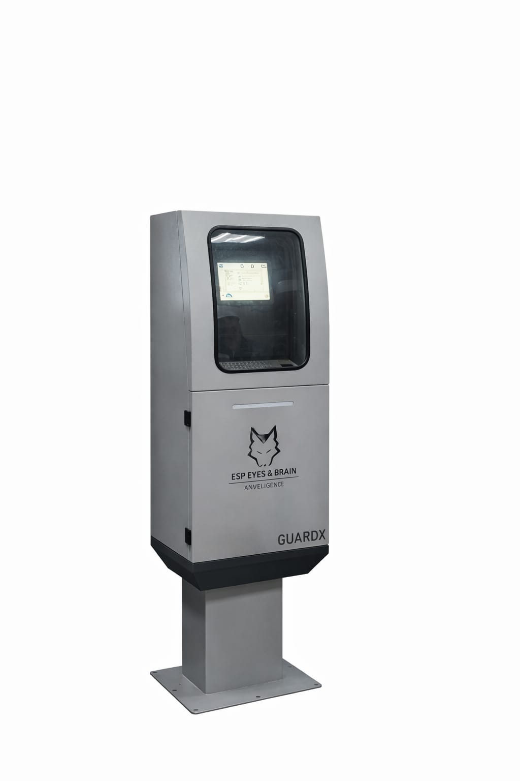
ESP-GUARDX ships as an integrated industrial appliance built from two enclosures (see the Hardware Block Diagram for the internal layout). Each unit includes:
| Specification | Details |
|---|---|
| Display | 10.1″ industrial touchscreen |
| Voltage channels | 18 (six rectifier boards × three voltage channels) |
| Current channels | 24 (six rectifier boards × four current channels) |
| Power supply | 10 A, 15 V card |
| Battery backup | 8-cell, 14 V, 150 Ah |
| Storage | Internal flash + SD card slot |
| Connectivity | USB, RS-485 |
Electrical Connections
Safety
De-energize the circuit and follow your site's lockout/tagout (LOTO) procedures before connecting or disconnecting voltage transformers, current transformers, or any power wiring. Live work on these inputs can cause electric shock and equipment damage.
Voltage and Current Inputs
The device accepts three-phase voltage and current inputs through instrument transformers:
- Voltage Transformer (VT): Steps down the motor voltage to a measurable range. The VT ratio is configurable in Settings.
- Current Transformer (CT): Steps down the motor current to a measurable range. The CT ratio and clamp type are configurable in Settings.
Typical ESP installation
A common setup uses a 1950:110 VT (ratio 17.73) and a 100:5 CT (ratio 20). Both ratios are entered in Settings > Main Settings after installation so that the device reports primary-side values.
Connection Topology
ESP-GUARDX supports:
- 3-Phase connections (standard for ESP motor monitoring)
- 1-Phase connections (for single-phase equipment)
The connection topology is selected in the Main Settings screen.
Sensor Inputs
Additional sensor inputs are available for:
- Downhole pressure and temperature sensors
- Wellhead pressure sensors
- Flow meters
- Vibration sensors
These connect via UART serial port with configurable baud rate, parity, and stop bits.
Ports
| Port | Function |
|---|---|
| USB | Data export, maintenance |
| RS-485 | Modbus RTU serial communication |