First Power On
Startup Sequence
When the device is powered on, ESP-GUARDX follows this startup sequence:
- System boot -- The embedded operating system initializes.
- Splash screen appears -- The ESP-GUARDX loading screen is displayed for approximately 3 seconds while the application initializes.
- Background preloading -- All major screens are preloaded in the background to ensure fast navigation later.
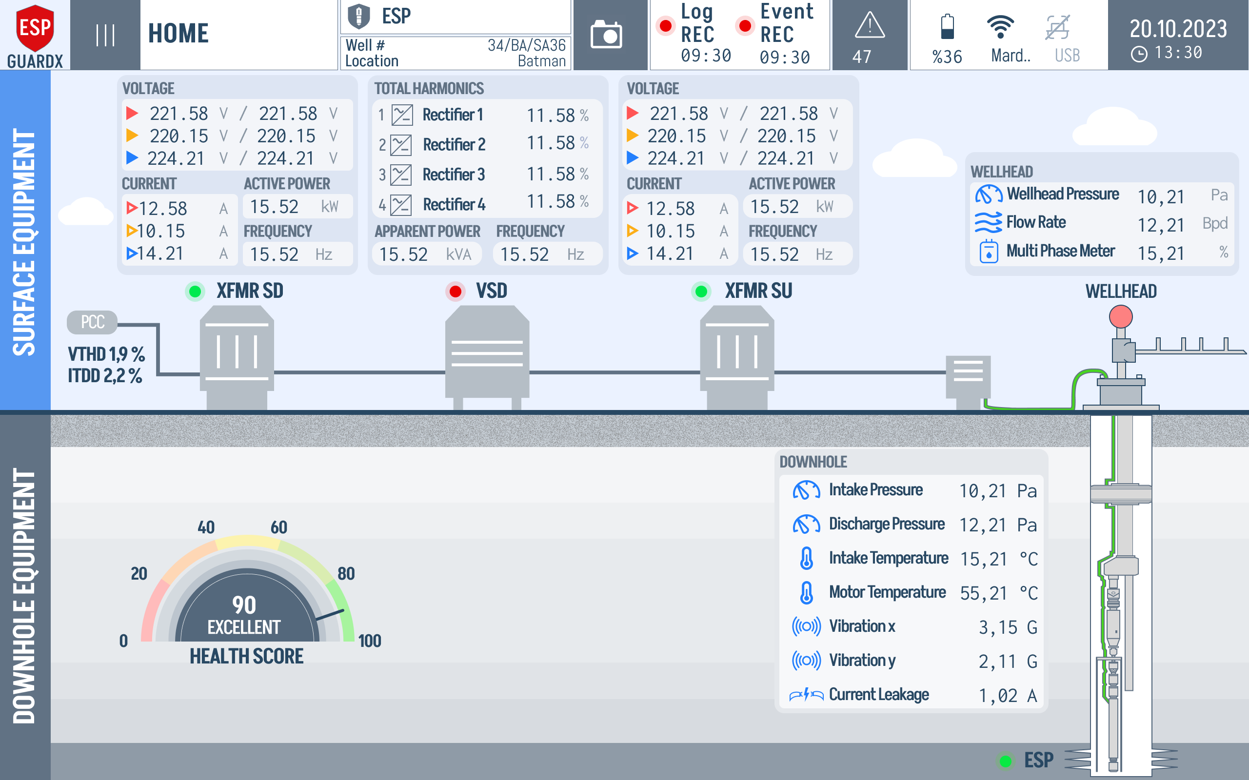
- Dashboard loads -- The main Dashboard screen appears and live data begins updating.
Note
The first navigation to any screen after startup may take 2--3 seconds as pages finish loading. Subsequent visits will be instant.
Initial Configuration Checklist
Before using ESP-GUARDX for monitoring, complete the following setup:
Step 1: Configure Main Settings
Navigate to Settings > Main Settings and configure:
- Connection Topology -- Select 3-Phase or 1-Phase
- Nominal Voltage -- Enter the system's rated voltage (e.g., 1950V for ESP motors)
- VT Ratio -- Enter the voltage transformer ratio
- Nominal Current -- Enter the system's rated current
- CT Ratio -- Enter the current transformer ratio
- Clamp Type -- Select the current measurement method
- Frequency -- Set the system frequency (30--400 Hz)
Step 2: Configure the ESP System
Navigate to ESP Configurator and enter:
- Well information (name, field, operator)
- Motor specifications (manufacturer, model, HP, voltage, current)
- Pump configuration (type, stages, impeller)
- Transformer details (KVA, impedance, pulse configuration)
- Cable specifications
Step 3: Set Event Thresholds
Navigate to Settings > Event Settings and review the default warn/trip thresholds for:
- Power parameters (voltage, current, frequency, power factor)
- Motor parameters (overcurrent, temperature, vibration, THD)
- Pump parameters (intake pressure, flow rate, efficiency)
- Well parameters (wellhead pressure, temperature, water cut)
Enable or disable individual event monitors as needed for your installation.
Step 4: Configure Communication
Navigate to Communication settings to set up Modbus RTU for connecting to other industrial devices (baud rate, parity, stop bits, slave address).
Step 5: Verify Data
Return to the Dashboard and verify that:
- Voltage readings match expected values
- Current readings are within normal range
- Frequency is correct
- All three phases are present and balanced
Display Brightness
The display brightness is controlled via PWM and can be adjusted in the Interface Settings. The brightness level persists across reboots.