ESP Configurator
The ESP Configurator is where every component in your ESP installation is defined. The values you enter here are what the rest of ESP-GUARDX uses for calculations, display labels, event context, health scoring, dashboard status, and optimization. Open it from the ESP Configurator item in the navigation sidebar.
Reading the Configurator Screen
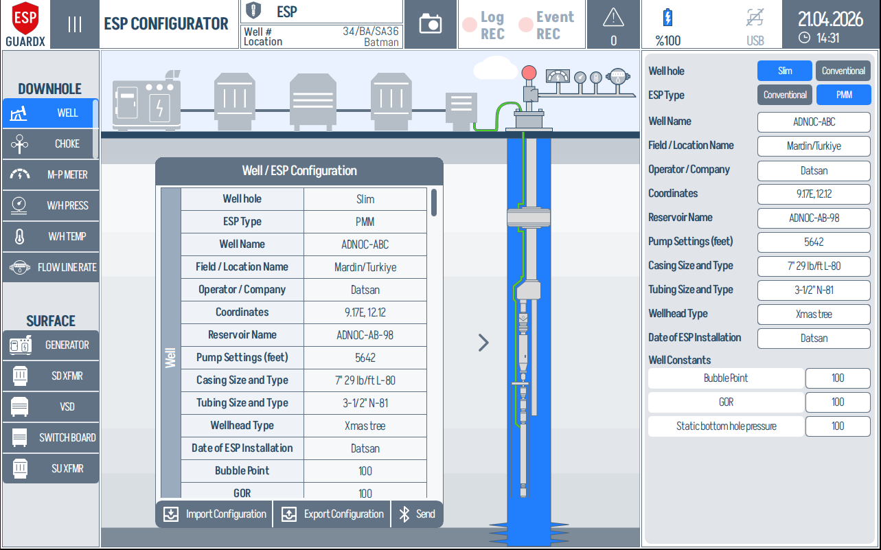
The screen is split into three working zones:
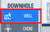
1. Components sidebar (left) - the component list is grouped into DOWNHOLE and SURFACE equipment. Tapping a row selects that component.
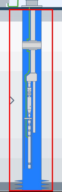
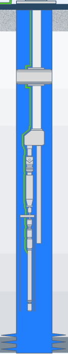
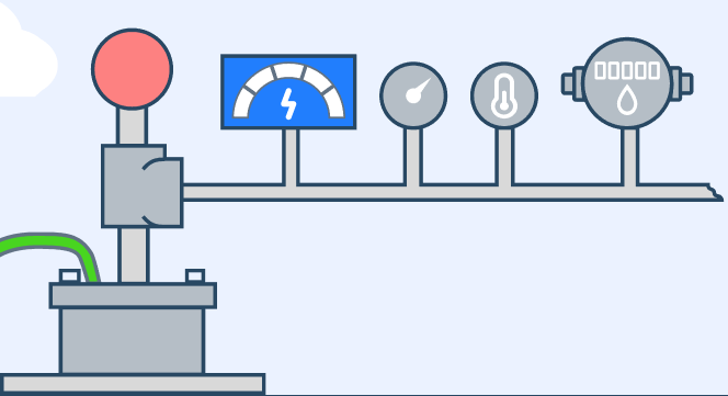
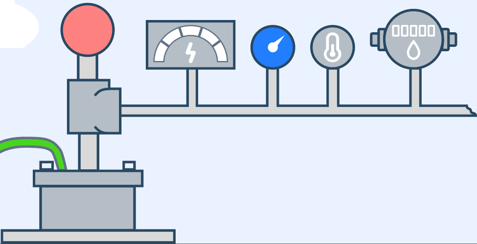
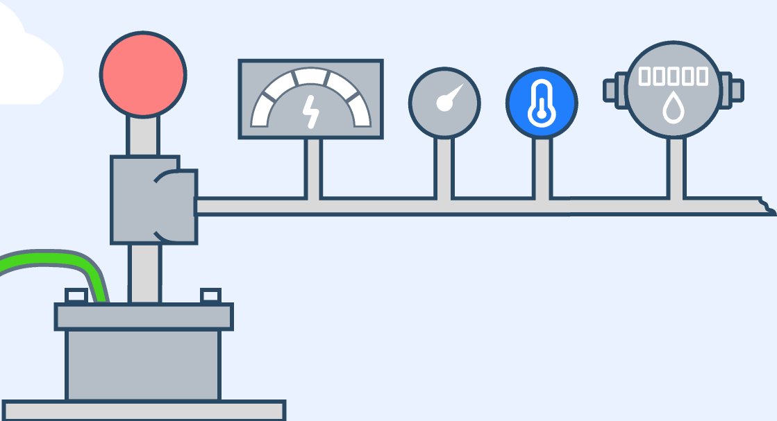
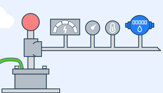
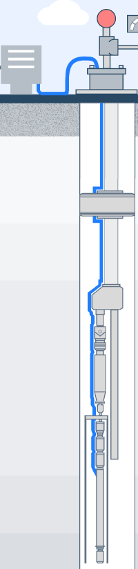
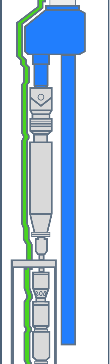
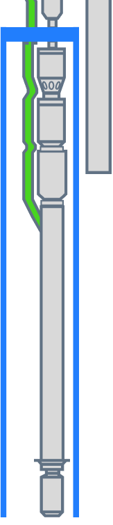
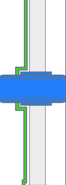
2. System diagram (centre) - the selected component is highlighted in the surface train or downhole assembly so you can confirm you are editing the correct item.
3. Configuration panel (right) - the field list changes with the selected component. These are the values the rest of the system treats as the configured equipment model.
Configuration Workflow
Across every component, the workflow is the same:
- Tap the component in the left sidebar.
- Confirm the highlighted location in the centre diagram.
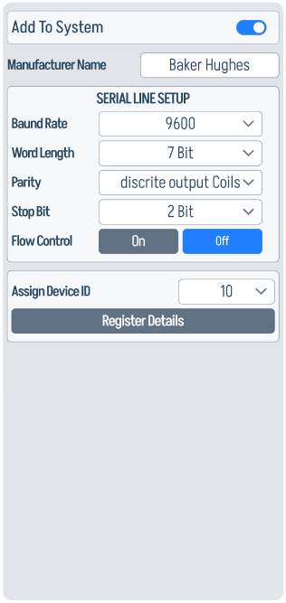
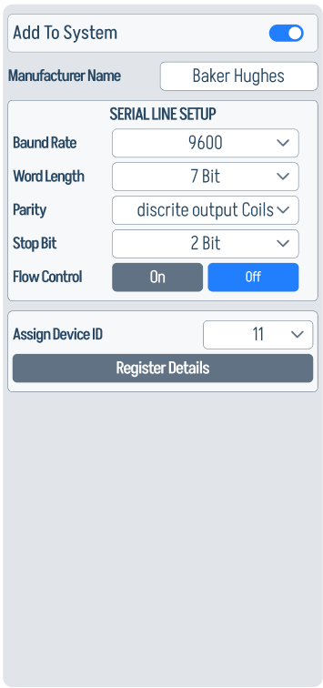
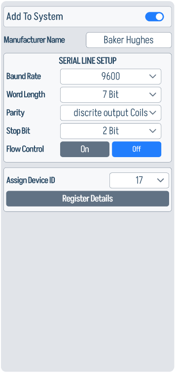
- Fill in the right-hand panel, starting with Add To System and the identifying fields.
- Configure serial communication and register mapping for live Modbus devices.
- Tap Send once the configuration is complete.
Save / Import / Export
The bottom of the centre column carries three workflow buttons that apply to the full configuration.

-
Import Configuration - load a saved
.xlsxor device backup so all component panels are populated at once.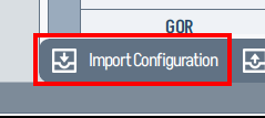
-
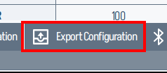
Export Configuration - save the current configuration to file, useful for cloning the same setup onto another well or keeping a backup before field changes.
-
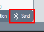
Send - commit the active configuration to the device and propagate it to Dashboard, Status & Power, Events, Pump, Motor, Well, and Optimization.
Excel import
Use the supplied Excel template when populating values offline. Sheet names and column headers must match what the configurator expects. Unrecognised columns are ignored, and missing fields stay blank until filled in on the device.
How Component Panels Work
The Qt application stores every panel as a component-specific configuration object. Some fields are identity fields, some are nameplate/geometry fields, and some are live communication fields.
- Add To System controls whether the component participates in monitoring, calculations, events, and Dashboard display.
- Manufacturer / model / type fields identify the installed equipment and are used in labels, reports, and curve lookups.
- Electrical, hydraulic, or mechanical ratings define the nominal values used by alarms, health scoring, pump curves, and optimization.
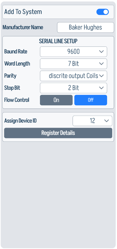
- Serial-line setup must match the connected device when a component supplies live Modbus data.
- Register Details opens the per-parameter Modbus mapping table for telemetry-producing devices.
Downhole and Wellhead Components
The downhole side defines the well geometry, production sensors, ESP string, and downhole electrical/mechanical equipment. These values feed the Well, Pump, Motor, Dashboard, Event, and Optimization screens.
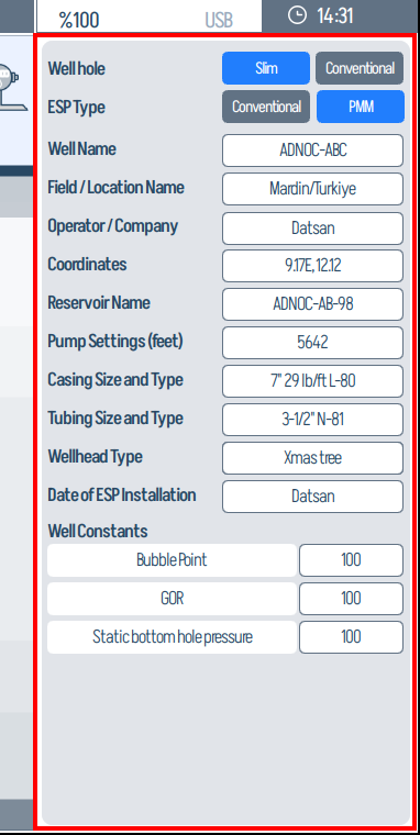
Well
The Well panel is the identity and reservoir baseline for the whole configuration. It records well type, ESP type, well name, field, operator, coordinates, reservoir name, installation depth, casing/tubing, wellhead type, installation date, bubble point, GOR, and static bottom-hole pressure.

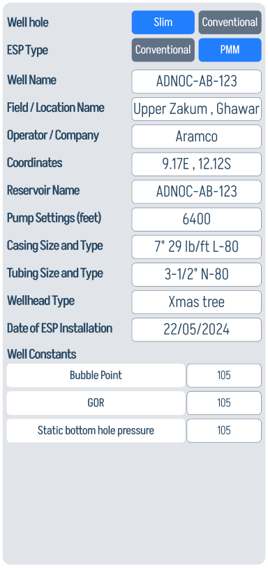
Use this panel before tuning pump or well analytics: the reservoir constants and installation geometry are reused by inflow/outflow logic, downhole interpretation, and production context.
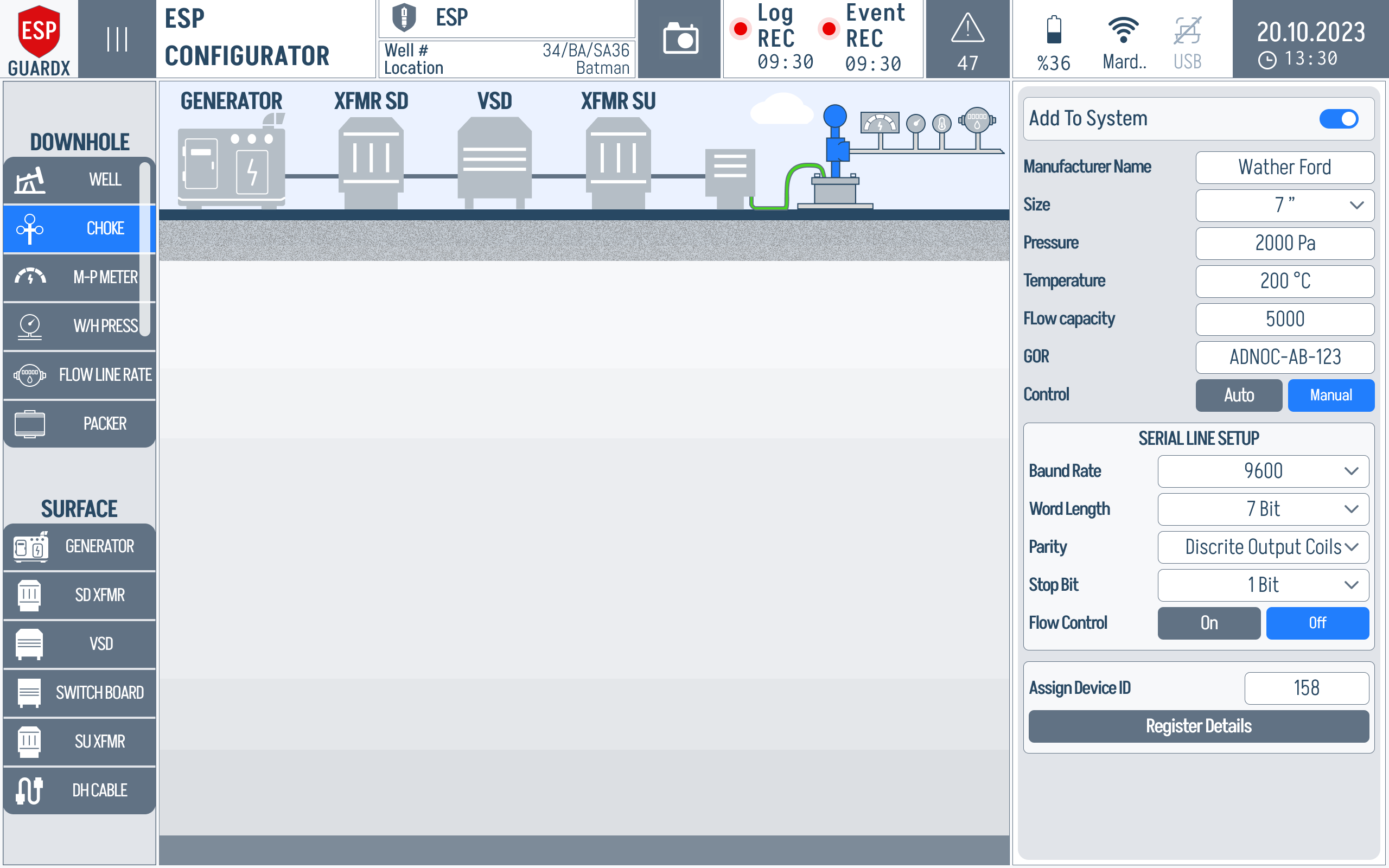
Choke
The Choke panel defines the wellhead control point: manufacturer, size, pressure, temperature, flow capacity, GOR, control type, and serial communication values.


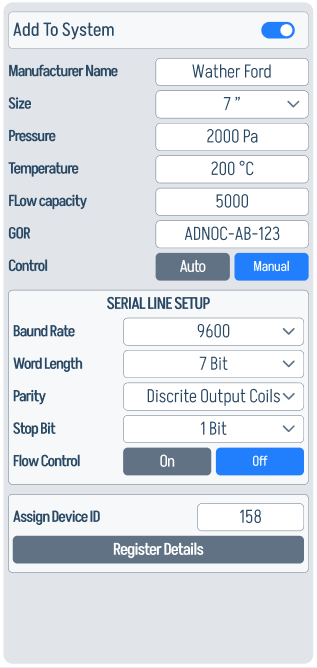
The choke values matter when the system compares surface restriction against flow, pressure drawdown, and optimization recommendations.
MultiPhase Meter
The M-P Meter panel is mostly a communications panel because the meter is a live production-data source. Confirm baud rate, word length, parity, stop bit, flow control, and device ID before trusting oil, gas, water, and flow-rate values elsewhere in the manual.

Wellhead Pressure Sensor
The W/H Press panel defines the wellhead pressure source and its Modbus address. This reading is used by production monitoring, well status, and optimization inputs.

Wellhead Temperature Sensor
The W/H Temp panel configures the wellhead temperature source. Keep the serial fields aligned with the physical instrument, otherwise temperature-dependent event thresholds and wellhead trend displays will be stale or blank.
Flow Line Rate
The Flow Line Rate panel configures the surface flow sensor downstream of the wellhead. It is one of the most important production inputs because Qflow is integrated into production totals and compared against pump, well, and optimization expectations.

Set the manufacturer and serial-line fields first, then open Register Details if the flow sensor exposes multiple parameters or custom register addresses.
Downhole Cable
The Downhole Cable panel records cable construction: type, voltage rating, AWG, current rating, insulation, armour, and lead type.

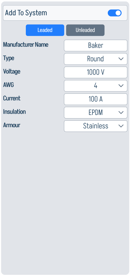
These ratings provide context for cable current leakage, voltage drop, and cable-condition diagnostics.
Advanced Gauge (ADV)
The ADV panel selects the advanced downhole gauge type, such as a shifting-tool configuration or conventional arrangement.


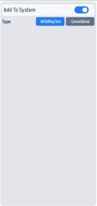
Enable this only when the installed completion includes that gauge or access arrangement.
Y-Tool
The Y-Tool panel records manufacturer, casing-size gauge, and tubing size for the bypass/access tool.

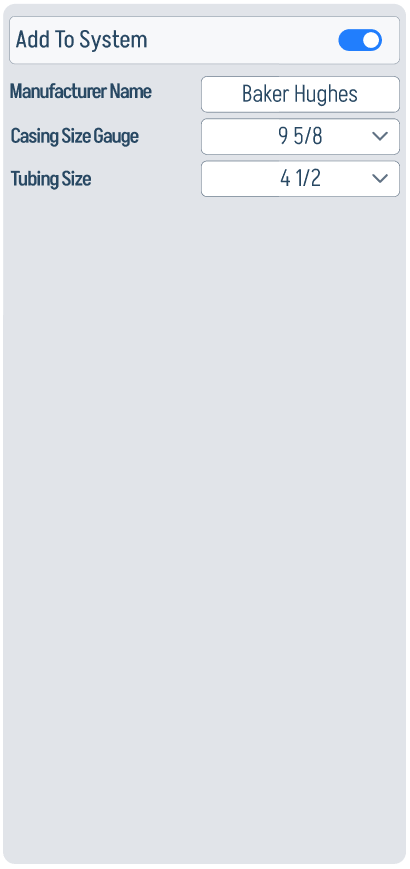
This configuration is mainly mechanical context, but it also helps operators confirm the displayed downhole assembly matches the actual completion.
Shroud
The Shroud panel records whether a shroud is installed and identifies its manufacturer.

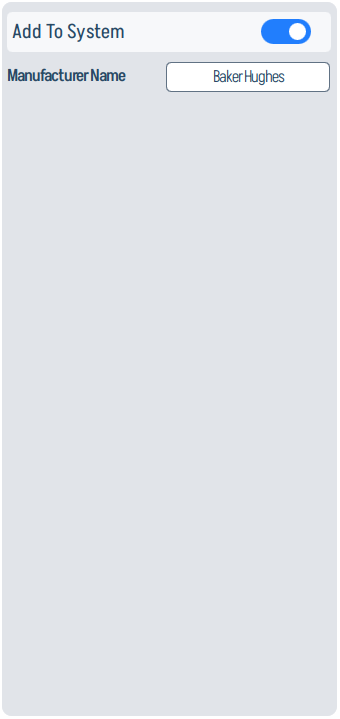
A shroud changes the physical intake and cooling arrangement around the ESP, so it should match the installed string before interpreting motor temperature and intake behavior.
Packer
The Packer panel captures the casing-size gauge for the packer location.

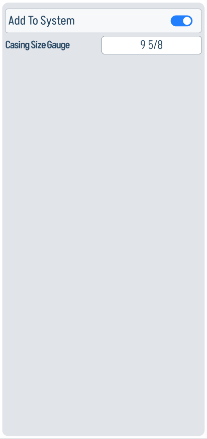
Use it to keep the downhole diagram and completion metadata aligned with the actual well.
Pump
The Pump panel is a core calculation input. It stores manufacturer, pump type, series, number of stages, number of tandem pumps, and impeller type.
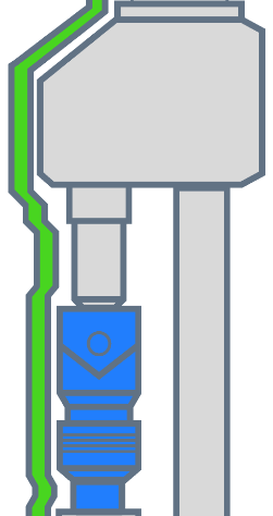
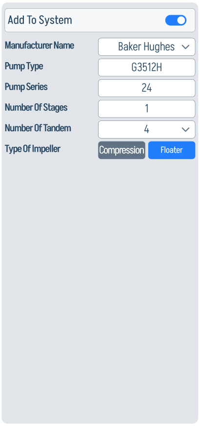
The selected manufacturer/type drives the pump-curve lookup. Stage count, tandem count, and impeller type affect head, efficiency, thrust-zone interpretation, and optimization recommendations.
GPU
The GPU panel records the gas-handling component in the downhole assembly: manufacturer, type, and shaft size.


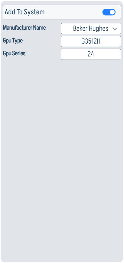
Keep this enabled only when the installed ESP string includes the GPU section shown in the diagram.
Gas Separator / Intake
The GS / Intake panel combines gas-separator and intake context. The gas separator stores manufacturer and GOR; the intake stores its manufacturer.


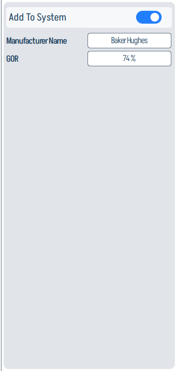
These values support gas-lock, intake-pressure, and underload interpretation.
Seal
The Seal panel defines the protector/seal section: manufacturer, seal type, series, number of tandems, selected tandem, and configuration type.


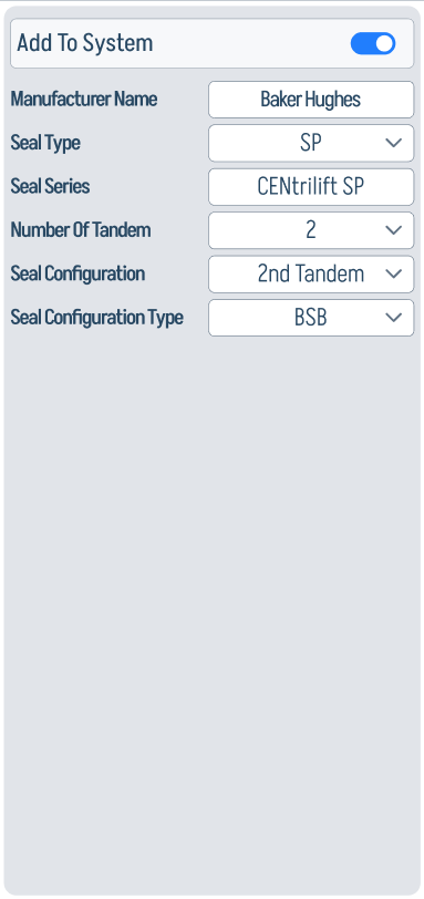
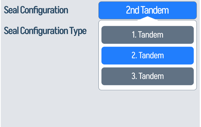
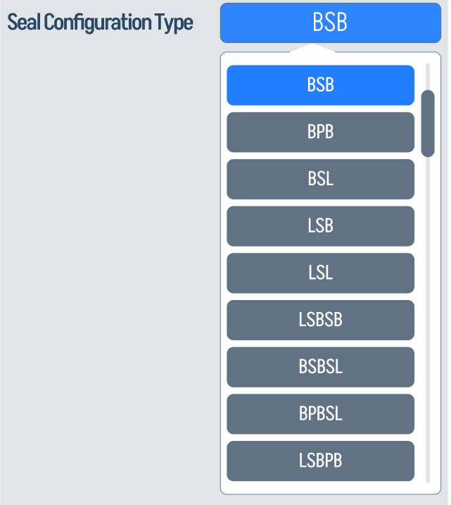
The tandem and configuration type fields should match the installed protector stack. They are useful context when reviewing seal temperature, pressure, and motor-oil/protector alarms.
Motor
The Motor panel records manufacturer, type, series, rated voltage, horsepower, current, frequency, and number of tandems.


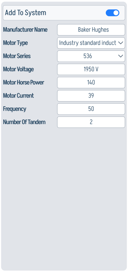
These nameplate values anchor motor-load, current, frequency, efficiency, phasor, and event-threshold interpretation.
Sensor
The Sensor panel defines the downhole sensor type and communication path. The app supports ground-fault/conventional selections plus baud rate, word length, parity, stop bit, flow control, assigned device ID, and register mapping.


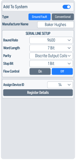
Use Register Details here when the sensor exposes pressure, temperature, vibration, leakage, or other downhole values at site-specific addresses.
Surface Components
The surface side defines the electrical supply path from generator/switchgear through transformers and VSD. These values drive Status & Power, Power Quality, PCC estimation, dashboard electrical charts, and electrical event thresholds.
Generator
The Generator panel records manufacturer, model, kVA, kW, frequency, output-voltage range, and ambient temperature.

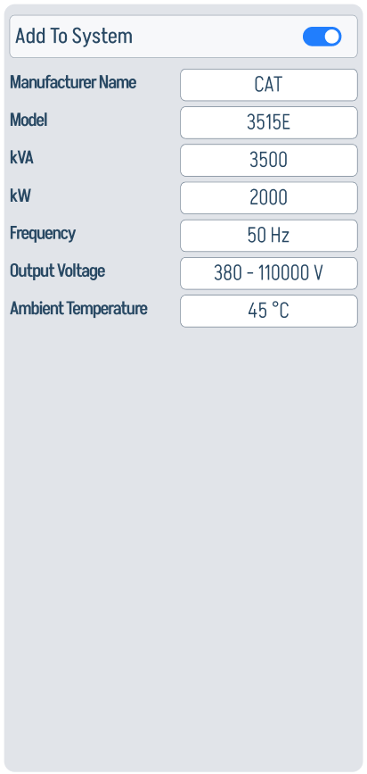
Use it when the ESP package is fed from local generation instead of a fixed utility source.
Step-Down Transformer (SD XFMR)
The SD XFMR panel records manufacturer, vector group, kVA, frequency, input/output voltage, impedance, ambient temperature, and pulse configuration.

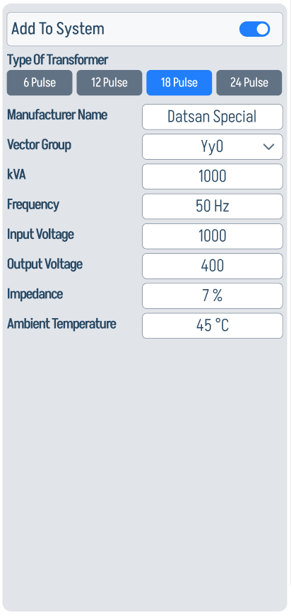
Vector group, impedance, voltage ratio, and pulse selection are especially important for PCC estimation and harmonic interpretation.
VSD
The VSD panel defines the drive: manufacturer, model, kVA, frequency, input/output voltage, ambient temperature, serial settings, and assigned device ID.


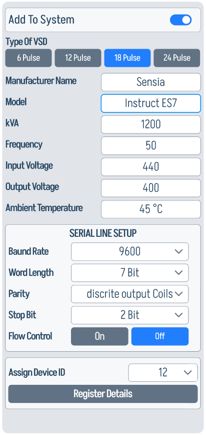
The VSD is the control point for frequency changes and the main source of many power-quality signatures, so its electrical ratings and communication fields need to be correct before using optimization or event playback.
Switch Board
The Switch Board panel stores manufacturer, model, kVA, frequency, input voltage, and ambient temperature.


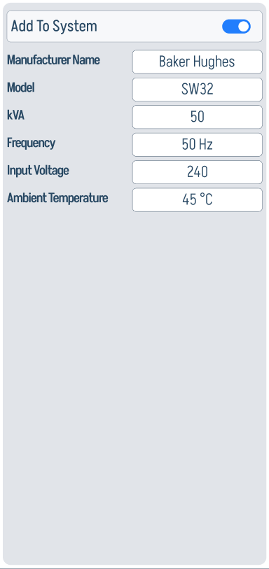
Use it as the surface switchgear reference for system one-line context and power-train metadata.
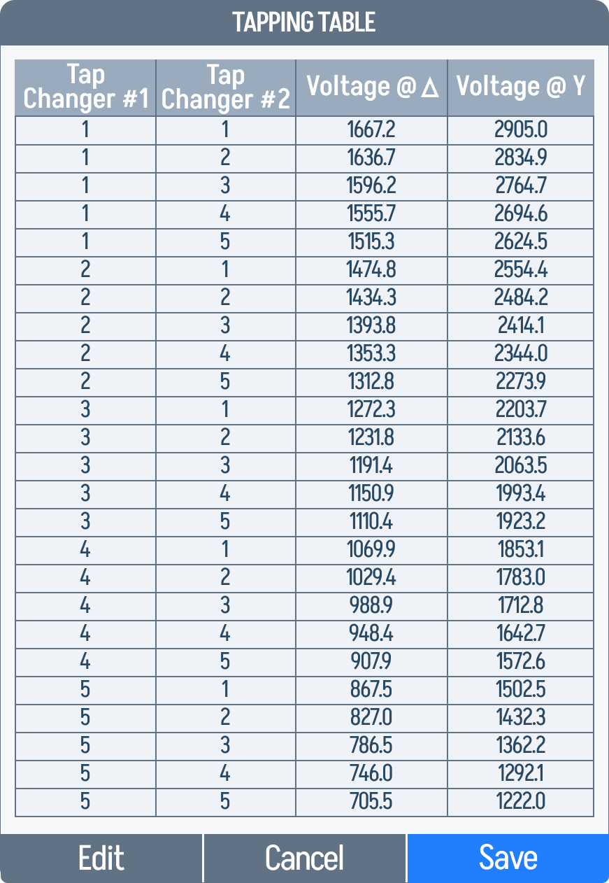
Step-Up Transformer (SU XFMR)
The SU XFMR panel records manufacturer, number of taps, vector group, frequency, input-voltage range, output voltage, impedance, and ambient temperature.


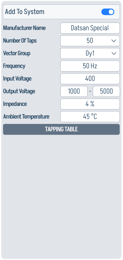
The SU XFMR ratio is used when comparing surface voltage against motor-terminal voltage. Tap-position data should match the physical transformer.

Modbus Register Details
For every component that talks Modbus, Register Details opens a per-parameter mapping dialog. Each row ties one monitored parameter to its slave register, command ID, register type, address, unit of measure, scale, and access mode.

The bottom row of the dialog is a set of action buttons:
Saving the Configuration
When every panel is filled in:
- Tap Send in the centre-bottom button row to commit the configuration to the device.
- Tap Export Configuration if you want a
.xlsxbackup before changing anything.
Saved data persists across reboots.
Next step
After saving, head to Event Settings to review and tune the warn / trip thresholds. Many thresholds are calculated as percentages of the nominal values you entered here.